
If we consider
a well trajectory from surface to total depth, it is helpful to look at the shallow
section and the intermediate and reservoir intervals separately.
The shallow
section, usually referred to as top hole, consists of rather unconsolidated
sediments, hence the formation strength is low and drilling parameters and
equipment have to be selected accordingly.
The reservoir
section is more consolidated and is the main objective to which the well is
being drilled, hence the drilling process has to ensure that any productive
interval is not damaged.
Top hole drilling:
For the very
first section of the borehole, a base from which to commence drilling is
required. In a land location, this will be a cemented ‘cellar’ in which a
conductor or

stove pipe will be piled prior to the rig moving in. The cellar will later accommodate the ‘Christmas tree’ (an arrangement of seals and valves to control production), once the well has been completed and the rig has moved off location.
As in the
construction industry, piling of the conductor is done by dropping weights onto
the pipe or using a hydraulic hammer until no further penetration occurs.
In an offshore
environment, the conductor is either piled (e.g., on a platform) or a
large-diameter hole is actually drilled, into which the conductor is lowered
and cemented.
Once the drill bit has drilled below the
conductor the well is said to have been spudded.
The top hole
will usually be drilled with a large-diameter bit (between 22 and 27 in.
diameter). The drill bit (roller cone type) will be designed to drill
predominantly soft formations.
As a result of the hole diameter and the rapid
penetration rate, vast quantities of drilled formation will have to be treated
and removed from the mud circulation system.
Intermediate and reservoir section:
Between the top
hole and the reservoir section, in most cases, an intermediate section will
need to be drilled. This section consists of more consolidated rocks than the
top hole. The deviation angle is often increased
significantly in this interval to reach the subsurface target, and lateral
departures from the surface co-ordinates may reach several kilometers.
Based on pore pressure prediction (from
seismic or measured data from offset wells) the mud weight has to be
determined. The pressure exerted by the mud column has to exceed the formation
pressure in order to maintain overbalance and prevent the hole from collapsing
but has to be lower than the fracture pressure of the formation.
If the formation strength is exceeded,
fracturing may occur, resulting in mud losses and formation damage.
Borehole/formation
stability is the realm of geomechanics. Challenges in well planning arise when
rock strength and thus borehole stability show considerable variations
depending on hole angle and direction, as shown in the Figure.
In this example, the small difference between
fracture gradient and collapse gradient at high deviation may require a
revision of the initially planned well trajectory through the intermediate
and/or reservoir section.
An
intermediate casing is usually set above the reservoir in order to protect the
water-bearing, hydrostatically pressured zones from influx of possibly over
pressured


hydrocarbons
and to guarantee the integrity of the wellbore above the objective zone. In
mature fields where production has been ongoing for many years, the reservoir
may show depletion pressures considerably lower than the hydrostatically
pressured zones above.
Before
continuing to examine the aspects of drilling through the reservoir, remember
that the reservoir is the prime objective of the well and a very significant
future asset to the company.
If the drilling
process has impaired the formation, production may be deferred or totally lost.
In exploration wells, the information from logging and testing may not be
sufficient to fully evaluate the prospect if the hole is not on gauge,
necessitating sidetracking or even an additional well.
On the other
hand, there is considerable scope to improve productivity and information value
of the well by carefully selecting the appropriate technology and practices.
Directional
drilling is usually done with a rotary steerable system. A downhole steering
and control unit is located in the near-bit assembly. A set of small
electronically controlled rotating stabilizer pads (actuators) exert a
continuous directional force onto a drive shaft which orients the drill bit
into the desired

direction. The
drill string is rotated at the same time, allowing hole cleaning.
A control unit
near the bit ensures that the hole angle is not increased or decreased rapidly
creating ‘dog legs’ which will result in excessive torque and drag. The rotary
steerable system is combined with logging tools in the drill string close to
the bit, allowing a continuous optimization of the well trajectory.
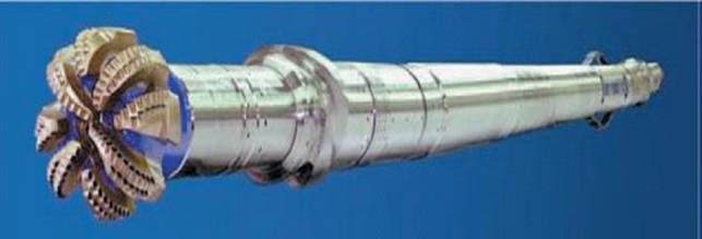
Mud turbines
and mud motors are also used for directional drilling. Rotational movement of
the drill string is restricted to the motor or turbine section, whilst the rest
of the drill string moves by ‘sliding’ or being rotated at a lower speed to
ensure hole cleaning.
In the example
of the turbine shown in the Figure, the mud is pumped between the rotor and the
stator section, inducing a rotational movement which is transmitted onto the
drill bit.
Motors and turbines are being replaced by the
rotary steerable system for cost and operational reasons. Their use is
increasingly limited to such applications as kicking off a sidetrack or where a
sharp change in angle is required in a short-radius horizontal well.
Advances in
drilling and completion technology today allow us to construct complicated
wells along 3D trajectories. In addition to vertical wells, directional
drilling allows us to build, maintain or drop hole angle and to turn the drill
bit into different directions. Thus, we are able to optimize the well path in
terms of reservoir quality, production or injection requirements. Sometimes
constraints at the surface (e.g., built-up areas) or subsurface (e.g., shallow
gas, faults, lenticular reservoirs) may require a particular well trajectory to
be followed.
The steering of
the well is supported by the stabilizers which form part of the drill string.
The blades can be activated and deactivated from the surface depending on
whether the angle is to be maintained, increased or decreased.
High deviation
angles (above 60) may cause excessive drag or torque whilst drilling and will
also make it difficult to later service the well with standard wireline tools.


Given the
lateral distribution of reservoir rock or reservoir fluids, a horizontal well
may provide the optimum trajectory. the Figure shows
the types of horizontal wells being drilled. The build-up rate of angle is the
main distinction from a drilling point of view. Medium radius wells are
preferred since they can be drilled, logged and completed with fairly standard
equipment. The horizontal drilling target can be controlled within a vertical
window of less than 2 m.

Improvements in this technology have greatly improved the accuracy
with which well trajectories can be targeted. MWD is achieved by the insertion
of a sonde into the drill string close to the bit. Initially providing only
directional data, the tools have been improved to the point where petrophysical
data gathering (gamma ray [GR], resistivity, density and porosity) can be
carried out whilst drilling.
Most reservoirs are characterized by marked lateral changes in
reservoir quality corresponding to variations in lithology. Computing tools now
commercially available allow the modelling of expected formation responses
‘ahead of the bit’.
This is possible in areas where a data set of the formations to be
drilled has been acquired in previous wells. The expected GR and density
response is then simulated and compared to the corresponding signature picked
up by the tool. Thus, in theory, it is possible to direct the bit towards the
high-quality parts of the reservoir.
Resistivity measurements enable the driller to steer the bit above
a hydrocarbon water contact (HCWC), a technique used, for example, to produce
thin oil rims.
These techniques, known as geo steering, are increasingly being
applied to field development optimization. Geo steering also relies on the
availability of high-quality seismic and possibly detailed paleontological
sampling.
تعليقات
إرسال تعليق